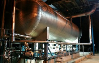
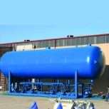
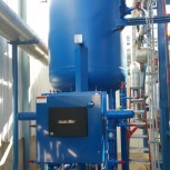
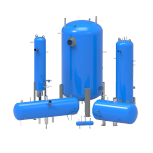
RVS’ MRP Recirculator System utilizes the highest quality and most advanced components available in the industry, and features the Matrix II Microprocessor™ Control Panel. The Matrix II has been engineered by RVS to provide total recirculator control, including liquid feed and level control, pump protection, pump bearing wear monitoring, and RVS’ patented pump bypass flow control.
The MRP Recirculator System with Matrix II™ is state of the art and backed by an industry exclusive and comprehensive 3-year warranty.
Standard catalogued models range in capacity from 56 to 5415 tons of refrigeration for ammonia depending on single or two stage system set-up, vertical or horizontal vessel orientation, evaporator temperature, and liquid supply temperature. Surge volumes of 10.5 to 761 cubic feet depending on vessel orientation. Pumped liquid maximum flow rates of 55 to 480 gpm depending on head pressure requirements. Optional factory assembled, single liquid feed assemblies range in capacity from 33 to 2710 tons of refrigeration for ammonia depending on evaporator temperature, liquid feed temperature, and valve train line sizing.
Matrix II Microprocessor™ Control Panel
- Faster processing speed and color HMI touch screen display
- Control and protection for up to six pumps plus a transfer pump
- Integrated pump bearing wear monitor on the display screen with safety cutouts and alarms
- Patented pump bypass flow control
- Pump differential pressure and current monitoring with safety cutouts and alarms
- Automatic operation of pumps and proportional liquid feed or solenoids valves
- Digital liquid level display on screen and high/low level monitoring with safety cutouts and alarms
- External communication and remote monitoring
- Factory wired, packaged, and tested – simple, ready to go installation with single point power connection
- See Bulletin 590 for more information on Matrix II
Patented Pump Bypass Flow Control
(U.S. Patent No. 7,437,880)
- Matrix II monitors pump flow and opens bypass only when necessary
- Eliminates the need to size the pump for continuous bypass flow
- More efficient operation requiring smaller, lower horsepower pumps
- Lifetime energy cost reduction over other manufacturers
Standard Vessel Design
- ASME, 250 psig, with dual vapor relief assembly
- National Board registration
- Stainless steel nameplate bracket and standoff to prevent corrosion
- Vertical or horizontal vessel configuration in 24” to 144” outside diameter range
- Internally routed minimum bypass flow, motor cooling, oil pot vent and relief line piping reduces insulation cost and potential for shipping damage
Liquid Level Column
- Level indicating column with valves, level eyes, frost shields, and oil drain
- Cable type, electronic level probe as standard
- High level shutdown float switch for compressor protection
Proportional Liquid Feed Assembly (Optional)
- Modulating valve minimizes pressure surges and protects pumps from cavitation
- Backup solenoid valve provides positive shutoff in the event of a power failure
- Can configured as a single or dual liquid feed assembly
Teikoku Pumps
- World’s largest manufacturer of hermetic pumps
- Exclusive bearing wear monitor at the pump and on the Matrix II display screen
- Secondary containment system eliminates leaks to atmosphere
- Low NPSH with capacities from 55-480 gpm in 460 or 575 volt service
- Motor cooling and individual minimum flow bypass lines piped internal to the main vessel
Oil Pot
- ASME, 400 psig, with single, replaceable, cartridge style vapor relief assembly set at 150 psig
- Relief discharge piped internal to the main vessel
- Optional dual relief assembly and/or relief to atmosphere
Finish
- Vessel hydrostatically or pneumatically pressure tested
- Factory package piping welded and tested in accordance with ASME B31.5
- Surface prepped to SSPC-SP6 and painted with high quality two component, high solids epoxy coating
- Entire assembly is evacuated to eliminate moisture and shipped with 15 psi dry nitrogen charge
- Exclusive and comprehensive 3 year warranty when equipped with the Matrix II Control Panel


